|
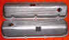
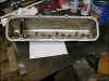
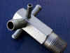
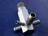
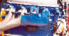
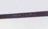
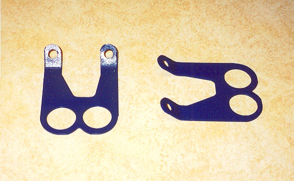
Valve Covers
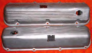
There were two versions of the 429 CJ/SCJ aluminum
finned 429 valve covers. The version used on the 1970 429 CJ/SCJ engine BOTH had twist type
holes (as shown above left). The 1971 429 CJ/SCJ valve covers (above
right) had a round hole in the passenger side valve cover and a twist type
hole in the drivers side valve cover. This was the version used on the '71
429 Mustang and Cougar (engineering numbers on my 71 429 Mustang valve
covers are Driver's side; D0OE-6583-A, Passenger side; D1OE-6583-CA).
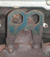
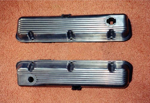
The two photos below show what the original finish looks like. After so
many years, many of these valve covers have been modified by being highly
polished, bead blasting or painting.

|
|
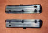
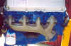
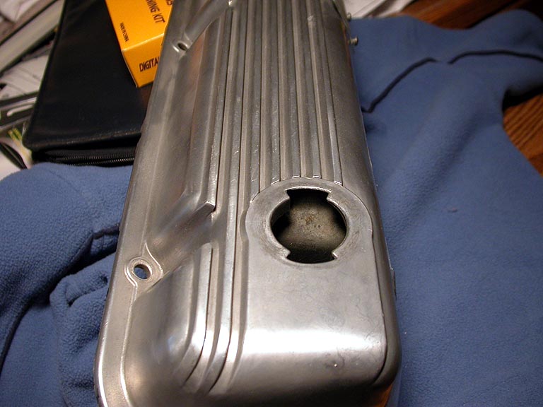
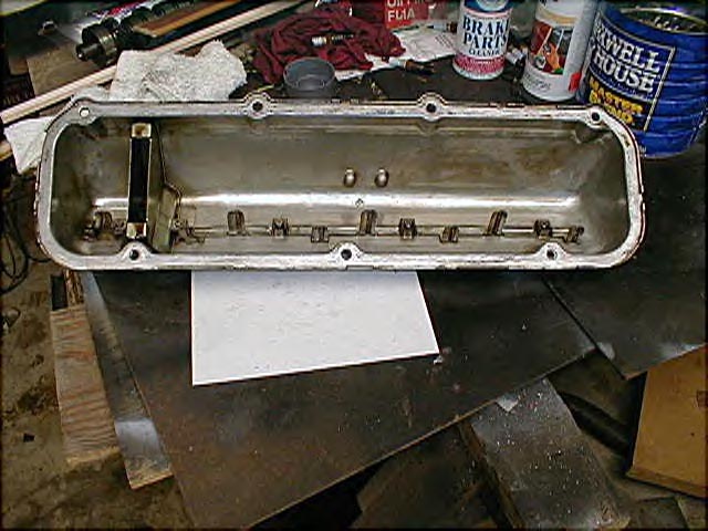
Valve Covers
The 429 aluminum valve covers had built
in drip rails to direct oil onto the rocker arms. The photos above show
close-ups of the drip rails.
|
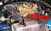
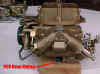
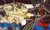
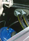
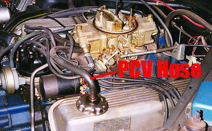
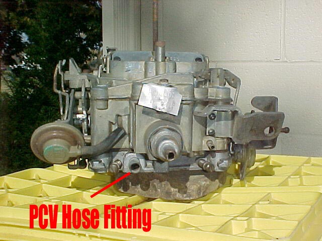
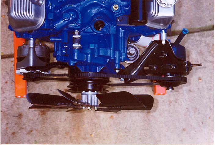
PCV Hose Routings
The photo above left shows the SCJ PCV Hose installed
and at right, the port on the Holley 780 that the PCV Hose attaches to.
Below left is the CJ PCV Hose installation and the Quadrajet port it hooks
to below right.
|
|
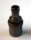
PCV Valve "C9TE"
This C9TE valve is listed in the MPC for the 429 SCJ.
The MPC also lists this valve as the "EV48".
|
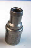
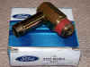
PCV Valve " D0AZ"
The D0AZ valve has a larger nipple than the C9TE. It is
the one listed for the 429 CJ application. The MPC lists this valve as the
"EV50".
|
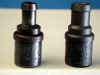
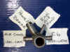
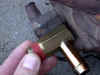
PCV Valve Comparison
This is a side by side comparison of the small nipple
C9TE valve to the large nipple D0AZ valve.
|
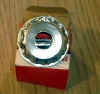

Valve Cover Cap
This is the Valve Cover Cap used on the driver's side
valve cover. A rubber grommet was inserted in the center to retain the PCV
valve. A plastic 90 degree elbow was placed in a plastic grommet in the
passenger side valve cover.
|
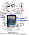
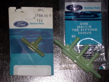
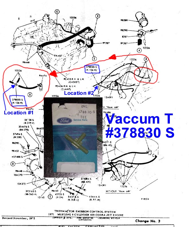
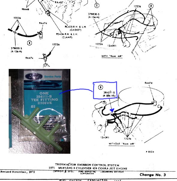
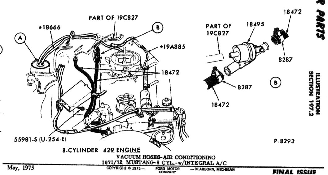
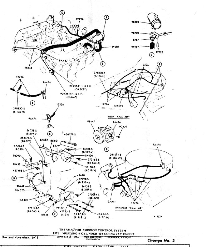
 Vacuum T's/Routings
The single T (at top left) is part of the rear vacuum hose
and provides a port to the ram air system in the hood. This fitting was also used at the one ram air hood flapper diaphram to port vacuum
to the other flapper diaphram (see diagram at center). A 5-port T (shown at right) is also
part of the 429 vacuum harness. The two diagrams show where it was used.
|

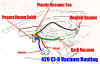
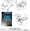
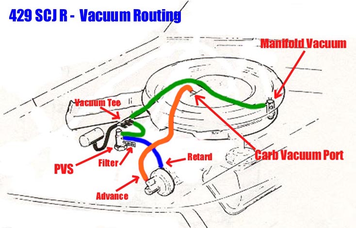
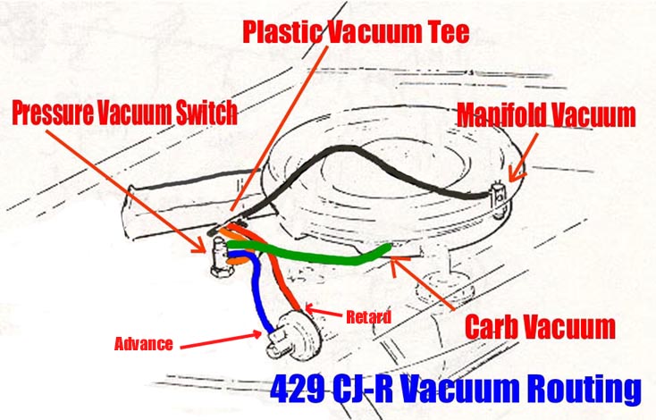
Vacuum Routings
The factory The vacuum hose routings for the 429 SCJ - R and CJ - R are also shown
above. Additional vacuum hoses for A/C are shown in the diagram left, but
the routing paths are not as clear as we would like. Additional research on
the A/C routing is needed. The 429 SCJ Non-Ram Air is shown in the diagram
below right.

|
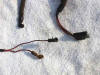
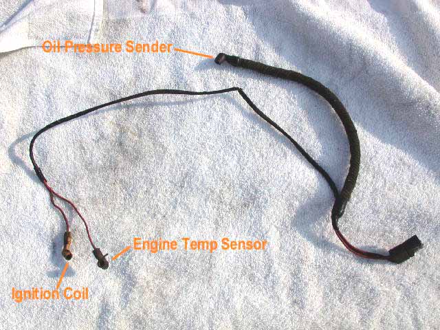
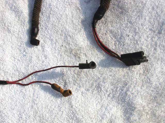
Engine Wiring Harness
This harness branches off the main harness at the
firewall and runs along the inside edge of the driver side valve cover. The
connectors are labeled as shown. Additional wiring variations exist for cars
with EPVS (electric pressure vacuum switch) and carburetor solenoids.
|
Front Intake Manifold Vacuum Fitting
The pictures above show the vacuum fitting used in the
front port of the 429 CJ/SCJ intake manifold. The photo at right shows a
comparison between an original 429 CJ/SCJ fitting (no beads on the ends of
the nipples) and the later model version used on the 460. The photo below
shows where this fitting installs in the intake manifold.
|
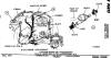
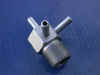
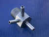
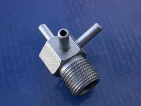
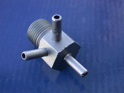
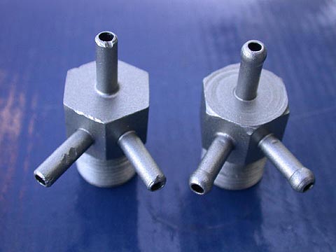
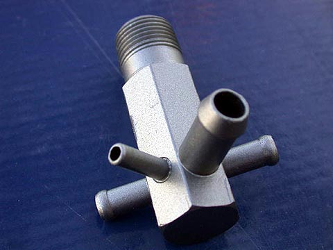
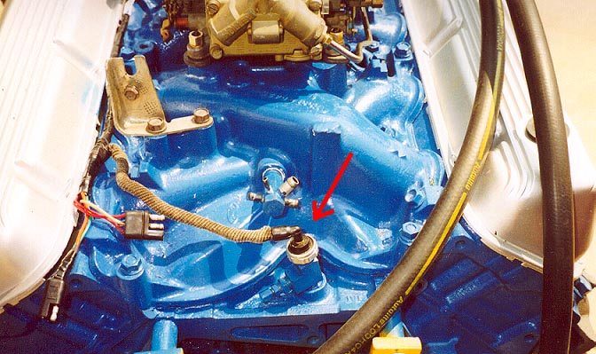
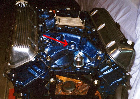
Rear Intake Manifold Vacuum Fitting
This large fitting was plumbed into the rear of the CJ/SCJ
intake manifold. On a CJ-R, the large nipple was for the power brake booster hose,
the small one for the Ram Air system and the two opposed fittings were
used for the C6 Modulator and the A/C vacuum can. The location
of this fitting is shown by the red arrow in the photo below.

|
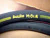
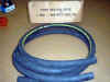
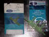
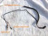
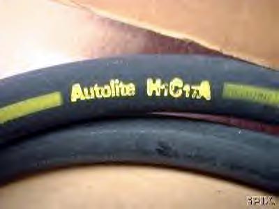
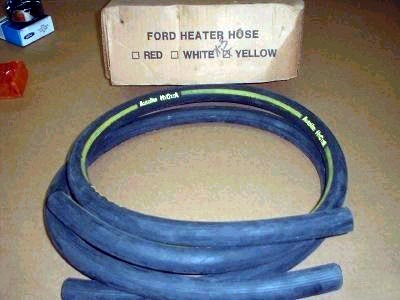
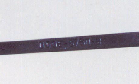
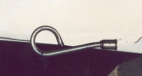
Heater Hose
The '71 Mustang/Cougar used the heater hose with the yellow
stripe. Note that although the 429 '70 Torino used a combination of metal
tubing and rubber heater hose, the 429
Mustang/Cougar used all rubber hose from the heater core to the fittings
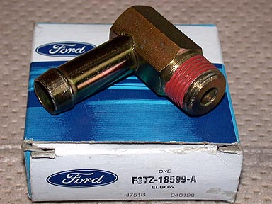
on the water pump and intake manifold. Below is the 90 degree fitting used
at the intake. You can buy an F3TZ-18599-A version of this nipple still at
the Ford dealer today - the same except the hose nipple is slightly
longer. It has been found that when one of these nipples rust out, they
both (the screw in 90 degree and the press-in straight nipple) need to be
replaced. Because of the long hose nipple on this 90 degree fitting,
it will probably hit the straight nipple when being screwed into the front
of the intake. To avoid this clearance problem, the 90 degee would need to
be installed first and then the straight press-in after that.
|
 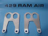
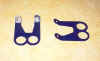
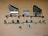
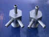
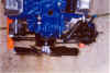
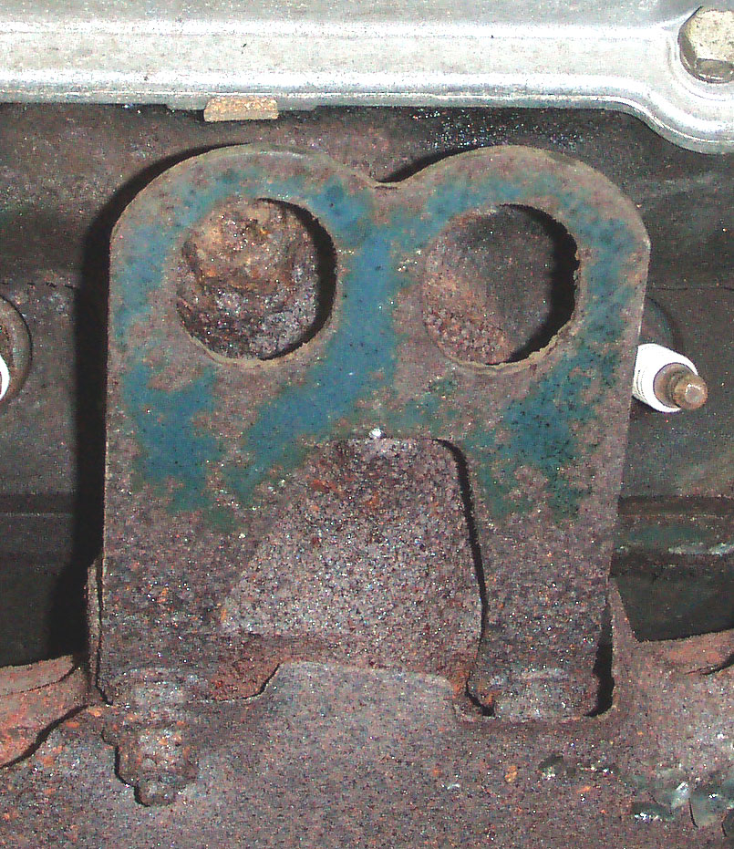
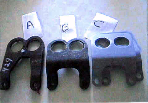
Engine Lift Hooks
The photos at top left and center show the correct 429 CJ/SCJ Mustang/Cougar lift
hooks. Note that one set has oval holes and the other set has round holes.
Since both versions have been found on what we believe to be original
engines, we are assuming there were two suppliers for these two
variations. The photo at top right is a comparison photo of various 429 lift hook
designs; (A) 429 CJ/SCJ Mustang, (B)
Base 429/460 (C) N Code 429 Cyclone
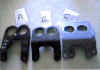
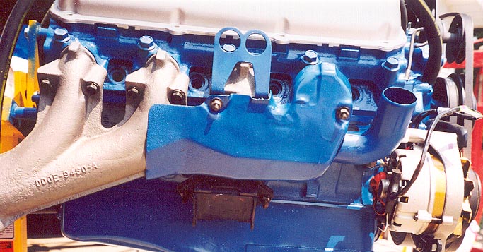
As shown above, the engine lift hooks attach at the second exhaust
manifold runner from the front of the engine for the passenger side and the 3rd exhaust manifold runner from the front
on the driver's side. They attached with the exhaust manifold bolts.
|
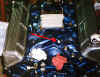
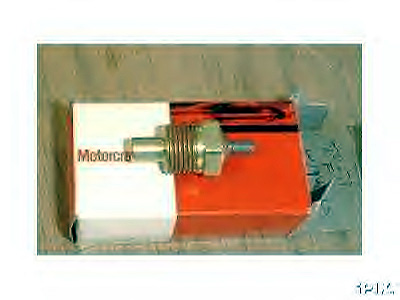
Senders
Temperature Sender
The Temperature Sender screwed into the threaded port
on the driver's side of the intake manifold as seen in the installed view
at right.
Oil Pressure Sender

The oil pressure sender threads into the top surface of
the block just behind the intake manifold.
|

This is the chrome Dipstick used on the
429 CJ/SCJ Mustang/Cougar (Part #D0OE-6750-B).
|

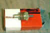
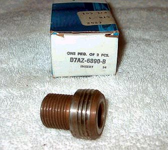
Oil Filter Fitting
This is the fitting (service part #D7AZ-6890-B) that
threads into the block that the engine oil filter threads on to.
|


